Your Complete Guide to
UV-C Air Purification
Everything you need to know before adding UV-C technology to your HVAC system—from how it works to choosing the right size, backed by ASHRAE engineering data and decades of hospital use.[1]
253.7 nm Peak UV-C Wavelength[2] 72% Below EPA Ozone Limit[3] 4–5× Air Recirculation / HourHow UV-C Works in Your HVAC System
Ultraviolet-C (UV-C) light at 253.7 nanometers damages the DNA and RNA of microorganisms, preventing them from reproducing.[2] In your HVAC system, a UV-C lamp serves two primary purposes:
Coil Irradiation (Primary Benefit) A UV-C lamp running 24/7 keeps your evaporator coil—the dark, damp surface inside your air handler—completely free of mold, bacteria, and biofilm. This is the application with the strongest scientific evidence and broadest professional consensus.[1][4] Airstream Treatment (Secondary Benefit) As air recirculates through your system 4–5 times per hour, it receives cumulative UV-C exposure with each pass. While single-pass effectiveness is limited at typical duct velocities of 500 feet per minute, the cumulative multi-pass effect provides meaningful air treatment over time.[5]"UV-C for surface irradiation works. Installer after installer confirms visible results: everywhere the UV light could reach—no mold. Where it didn't reach—mold."
— Professional HVAC Installer Forum Consensus[6]Hospitals have relied on UV-C germicidal irradiation for over 80 years.[7] The same technology, properly sized for your home, prevents your HVAC system from becoming a contamination source. BioShieldUV systems produce just 0.014 ppm ozone—72% below the EPA's safety threshold of 0.05 ppm.[3]
 Surface Test Results: Evaporator coil with UV-C treatment vs. without Image: Field Controls. Left: coil treated with FlexMountUV shows minimal biological growth. Right: untreated coil shows significant contamination on surface test plates.
 The Difference UV-C Makes: Before & After
These real-world photos show what happens to evaporator coils with and without UV-C treatment. The results apply to both supply-side and return-side installations—the coil surface is irradiated regardless of lamp position.
 Before UV-C — heavy mold & biofilm
Source: UVDI.com
 After 2 months of UV-C treatment
Source: UVDI.com
 After 7 months — fins fully restored
Source: UVDI.com
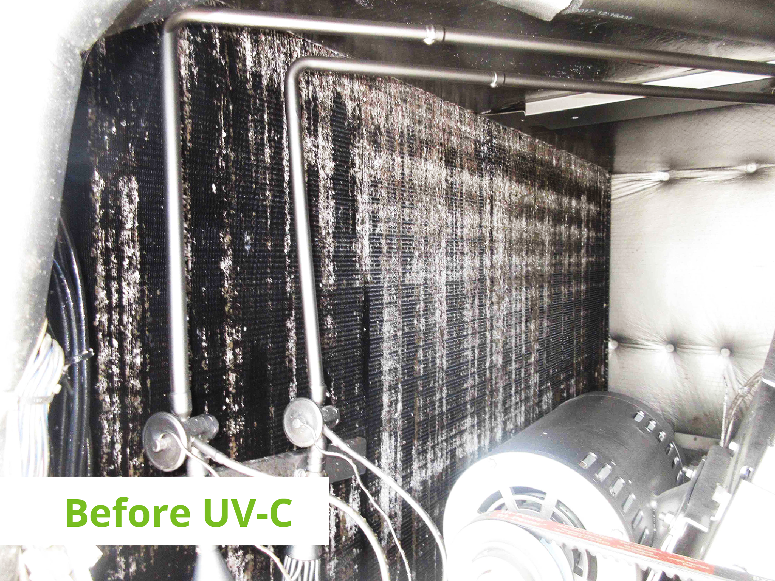 Commercial AHU — before UV-C
Source: EMC LLC
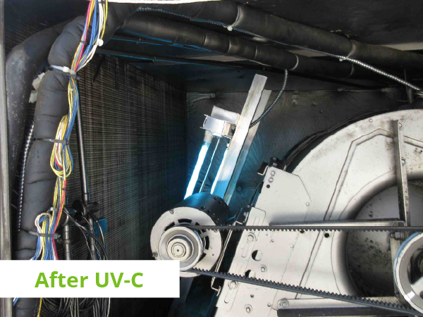 Same AHU — after UV-C treatment
Source: EMC LLC
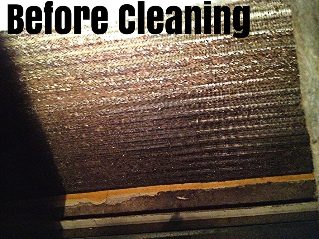 Before — heavy contamination
Source: Mission AC
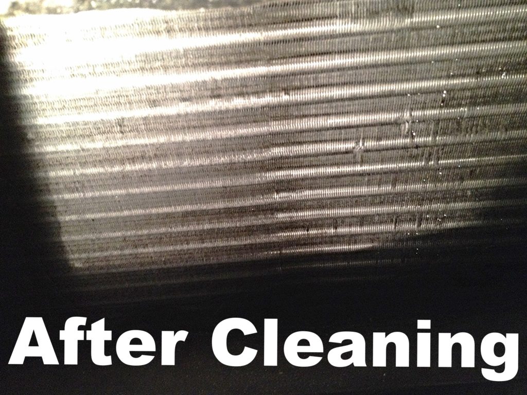 After — fins fully restored
Source: Mission AC
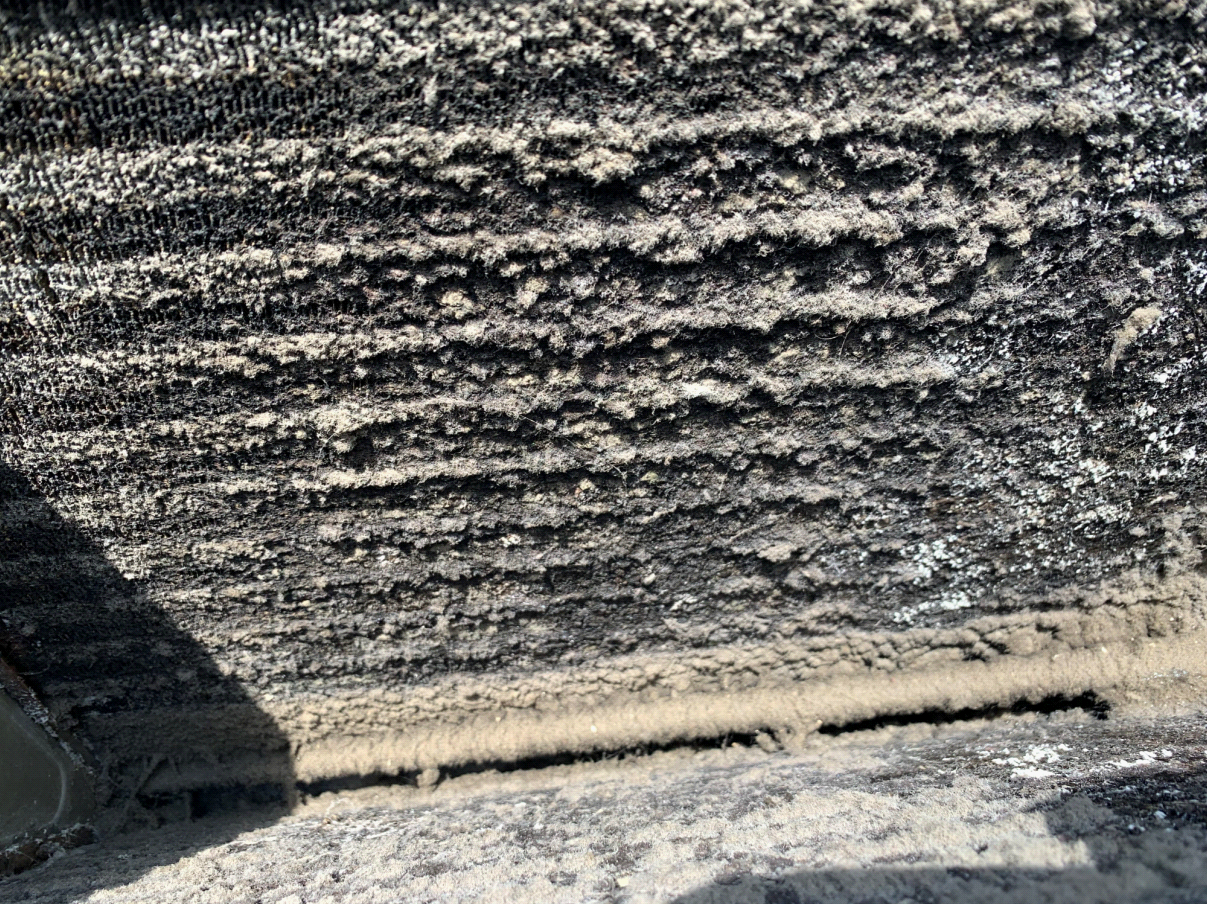 Dirty coil close-up — thick biofilm
Source: All-About-The-House.com
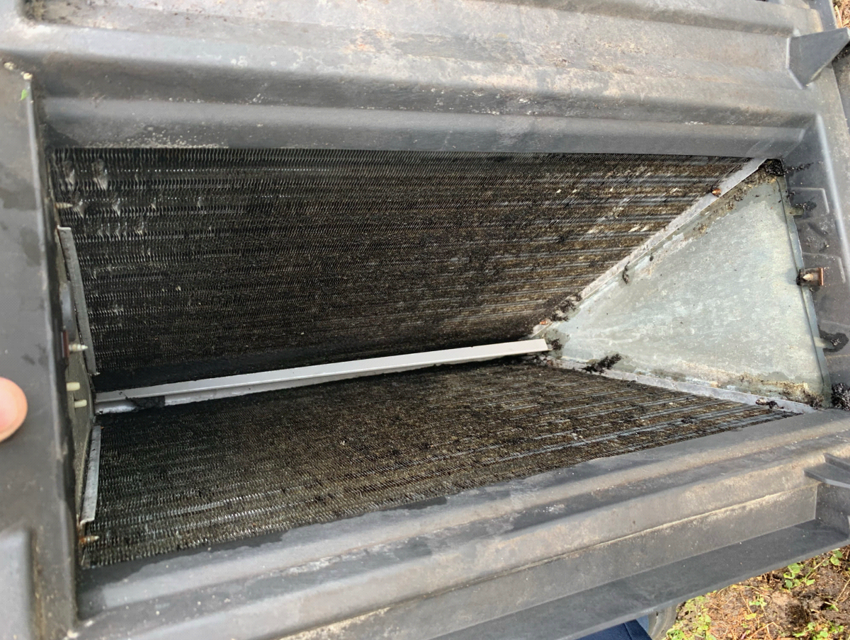 A-coil caked with buildup
Source: All-About-The-House.com
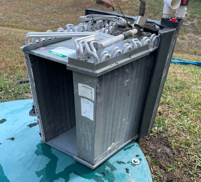 Clean coil — UV-C maintains this
Source: All-About-The-House.com
 Lab Culture Test: Mold growth before vs. after BioShield UV-C Left petri dish shows typical mold colonies cultured from an untreated A/C system. Right dish shows the same test after BioShield UV-C installation—virtually zero growth.
 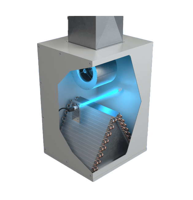 UV-C lamp inside air handler (cutaway)
Image: AprilAire
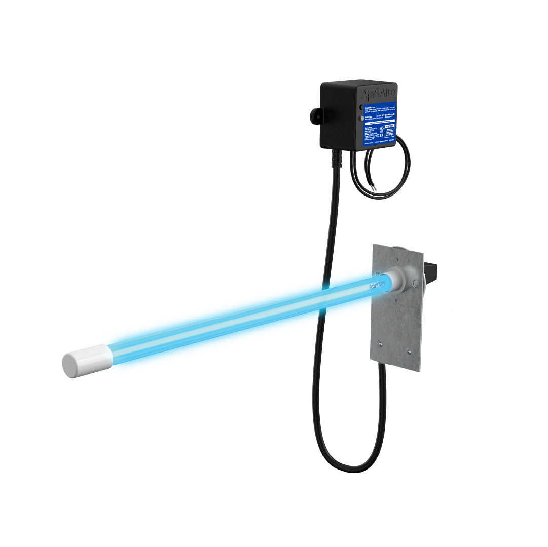 Typical dual-bulb UV-C lamp system
Image: AprilAire
 Magnetic-mount UV lamp (no drill)
Image: Field Controls BioShieldUV Ozone Output vs. EPA Safety Limit BioShieldUV 0.014 ppm EPA Safety Limit 0.05 ppm BioShieldUV systems produce just 0.014 ppm of ozone — 72% below the EPA safety threshold of 0.05 ppm.
Is UV-C Right for Your Home?
UV-C technology works best as a supplement to good filtration, duct sealing, and humidity control—not a replacement for them.[1] Start by identifying your primary concern:
Mold or Musty Odors Best candidate for UV-C. Your evaporator coil is the primary breeding ground for mold and bacteria in any HVAC system. A UV-C lamp running continuously eliminates this growth—often called "dirty sock syndrome." This is where UV-C has its strongest evidence base.[1] Allergies, Asthma, or Immune Concerns Strong candidate: UV-C + MERV 11+ filter. UV-C alone won't capture particulate allergens, but keeping your coil clean prevents the system from becoming a contaminant source. Pair with enhanced filtration for the best results.[8] General Air Quality & Pathogen Concerns Set realistic expectations. At 500 feet per minute of duct velocity, single-pass exposure is brief. However, your air recirculates 4–5 times per hour, providing cumulative treatment. UV-C delivers proven coil cleaning plus meaningful ongoing air treatment.[5] Odors & Chemical VOCs Limited UV-C capability. UV-C effectively addresses biological odors (mold, mildew) but chemical VOCs require photocatalytic oxidation (PCO) or activated carbon technology. Be honest with yourself about what you're trying to solve.[9]When UV-C Might Not Be the Right First Step
Some homes need other improvements before UV-C will deliver meaningful value. The indoor air quality industry's "big three" fundamentals are filtration, ventilation, and humidity control—UV-C comes after these are addressed.[1]
Leaky Ductwork If your ducts have leaks, seal them first. Interestingly, UV-C can help diagnose this: turn the lamp on at night and look for light escaping through duct seams.[6] Oversized HVAC System An oversized system short-cycles, preventing proper dehumidification. UV-C won't fix a fundamental sizing issue—consult an HVAC professional about fan speed adjustments first.[10] Flex Duct in Line-of-Sight UV-C degrades polymer inner liners in flexible ductwork. Flex duct must be shielded or the lamp repositioned. This doesn't necessarily disqualify your home, but requires proper planning.[11] Pre-2013 Drain Pan Older drain pans may become brittle under UV exposure. One professional noted they can "turn into jelly" if the lamp is within 12 inches. Have your installer verify the pan material before installation.[6] Basic Fiberglass Filter Only If you're still using a $2 fiberglass filter, upgrade to a MERV 11+ media filter before investing in UV-C. Good filtration is the foundation of indoor air quality.[8] Dry Climate, No Mold History UV-C delivers its strongest return on investment in humid climates (Florida, Gulf Coast, Southeast). In arid regions with no visible mold or odor issues, the benefit-to-cost ratio drops significantly.[12]Choosing the Right BioShieldUV System
The ASHRAE-derived industry standard for coil irradiation is approximately 7.5 watts of UV-C per square foot of coil face area, targeting a minimum irradiance of 50–100 µW/cm².[1] For residential systems, this translates to wattage recommendations based on your HVAC tonnage, since tonnage determines coil size.
7.5 W Per sq ft of coil face[1] ASHRAE standard for coil irradiation 12,000 µW/cm² per 1,000 CFM[5] Airstream disinfection (much higher) 50–100 µW/cm² minimum irradiance[1] Across the entire coil face Recommended UV-C Wattage by HVAC System Size| Model | Wattage | System Size | Home Size | Airflow | Min Clearance |
|---|---|---|---|---|---|
| S18 / SL18 | 18 W | 1.5–2 ton | ≤1,200 sq ft | 600–800 CFM | 7″ / 18″ |
| S36 / SL36 | 36 W | 2.5–3 ton | 1,200–1,800 sq ft | 1,000–1,200 CFM | 10″ / 23″ |
| S72 | 72 W | 3.5–4 ton | 1,800–2,400 sq ft | 1,400–1,600 CFM | 17″ |
| S72+ | 100 W | 4–5 ton | 2,400–3,000 sq ft | 1,600–2,000 CFM | 17″ |
| Dual S72 | 144 W | 5+ ton | >3,000 sq ft | 2,000+ CFM | 17″ each |
Classic Series vs. Magnetic Series
Classic Series (S18 / S36 / S72) Permanent drill-mount installation. The lamp protrudes through a drilled hole while the ballast stays external. Requires less clearance (7"–17"). Best for professional installations and long-term setups. Most secure and vibration-resistant attachment. Magnetic Series (SL18 / SL36) No-drill, renter-friendly installation. Entire assembly mounts inside the duct using magnets. SL18-WallPlug: simple 120V plug-in. SL18-HVAC: powered by existing 24VAC transformer. Requires ferrous metal duct surface (test with a magnet) and 18"–23" clearance. Important fit note: The Magnetic Series requires the entire lamp assembly to fit inside the duct (18–23" clearance), while the Classic Series only needs the lamp to protrude through a drilled hole. This is the most common sizing mistake—always measure your internal duct dimensions before choosing.What These Systems Look Like
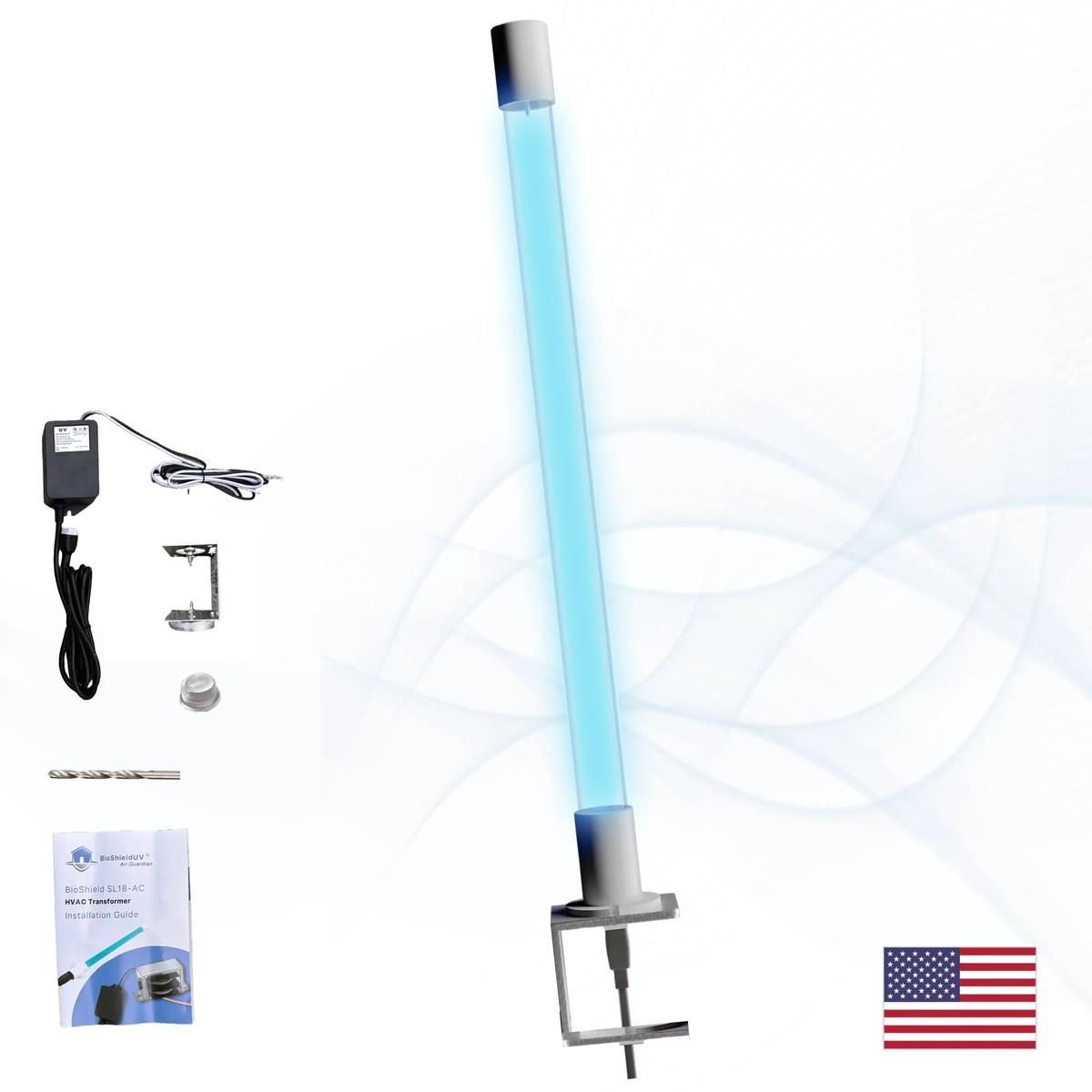 BioShieldUV Magnetic Series
Image: bioshielduv.com
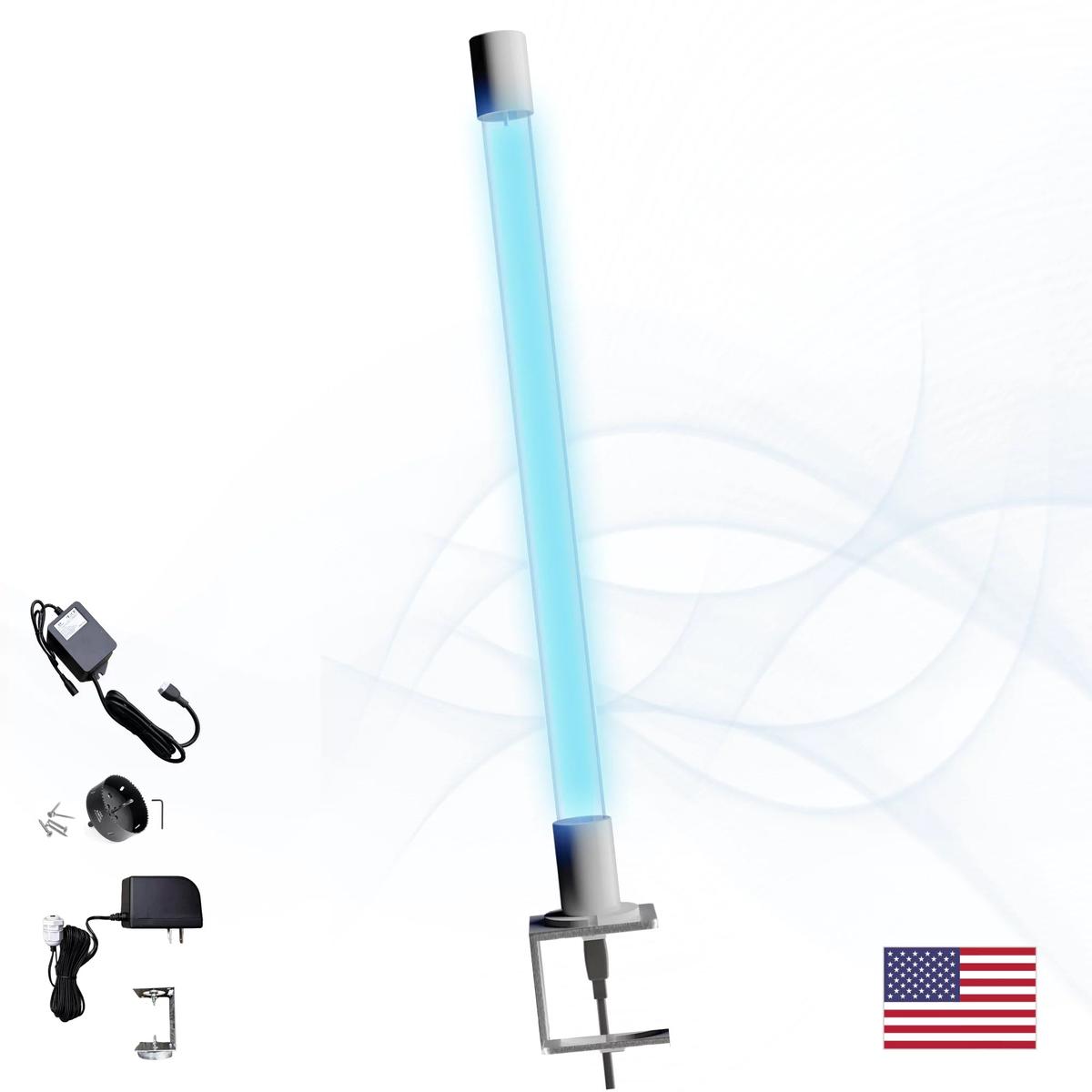 Magnetic Mount Detail
Image: bioshielduv.com
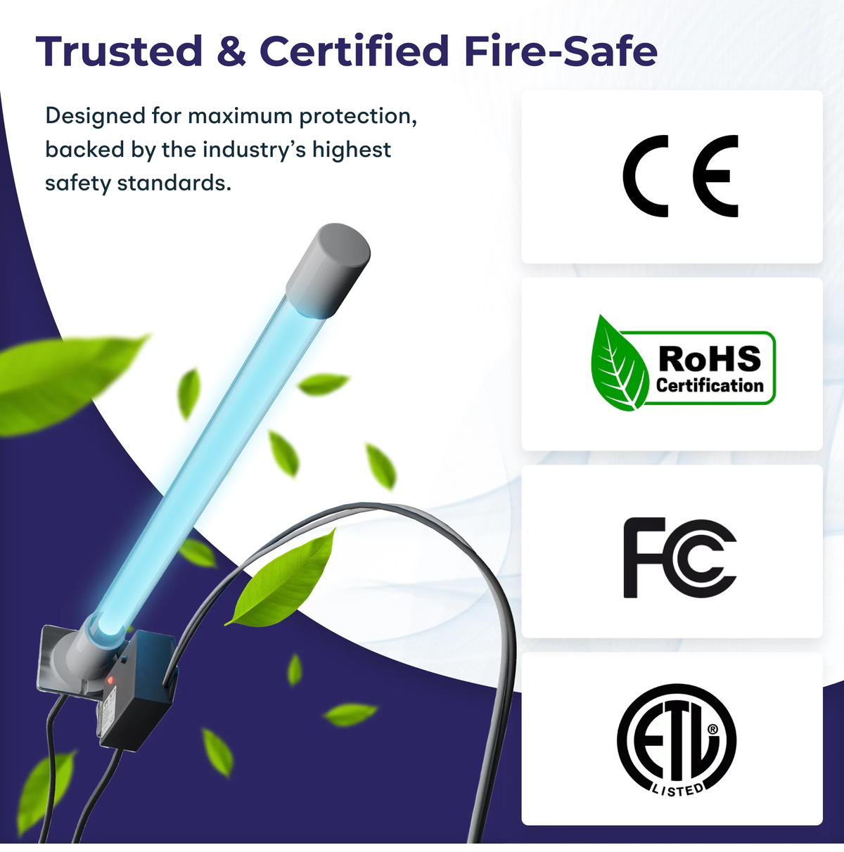 Full Product Lineup & Certifications
Image: bioshielduv.com
 Single-bulb classic mount (53W)
Image: Bryant/Carrier
 Double-bulb for larger systems
Image: Bryant/Carrier
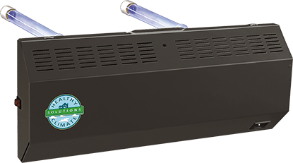 Lennox Healthy Climate UV
Image: Lennox
 Magnetic mount system with power supply
Image: LSE Lighting
 Easy-install on-coil UV light
Image: UV Light Solutions Installation Approach: Key Differences
| Metric | Classic Series | Magnetic Series |
|---|---|---|
| Minimum Clearance lower is better | 7 in ✓ Better | 18 in |
| Install Difficulty (1–10) lower is better | 6 | 3 ✓ Better |
| Vibration Resistance higher is better | 9 ✓ Better | 5 |
| DIY Friendliness higher is better | 4 | 9 ✓ Better |
What to Know About Installation
Most UV-C guides give one simple rule: “install on the supply side, above the coil.” That works for some systems, but it’s an oversimplification. The truth is, there are two separate placement principles at work, and understanding both will help you—or your HVAC contractor—find the ideal location for your specific system.
Two Principles That Determine UV-C Placement
1 Illuminate the Coil Surfaces PrimaryThe evaporator coil is ground zero for biological growth. Hundreds of thin aluminum fins are constantly wet during cooling season, creating a dark, damp environment where mold and biofilm thrive. When these organisms colonize the coil, they form an insulating layer that reduces heat transfer and restricts airflow.
5–8°C operating temp increase from biofilm buildup 10–25% potential energy cost increase over time 25% longer compressor run cycles from fouled coils The key: Position the lamp where it has direct line-of-sight into the interior cavity of the A-coil—the V-shaped pocket between the two coil slabs. This inner pocket has the most concentrated surface area and is the darkest, most mold-prone zone. Shining UV-C into this cavity gives you maximum coverage across both coil slabs simultaneously. 2 Cover the Drain Pan SecondaryThe condensate drain pan sits below the coil and collects moisture that drips off during cooling. Standing water creates ideal conditions for mold, algae, and bacteria. A neglected drain pan produces musty odors and can spread biological growth back up to the coil. If your single lamp can illuminate both the coil and the drain pan, that’s ideal. But if you have to choose, prioritize the coil.
Why coil first? The coil has vastly more surface area than the drain pan, is directly responsible for heat exchange efficiency, and biofilm on coil surfaces has a cascading effect on your entire system—higher energy bills, restricted airflow, shortened equipment life. The drain pan matters, but its impact on system performance is less dramatic. With a single lamp, experienced installers position it to cover the coil first and the drain pan as a bonus.Applying These Principles to Your Air Handler
The “best” UV-C placement changes depending on how your air handler is oriented, because the relationship between the coil, the drain pan, and the direction of airflow shifts with each configuration. Below are the three most common setups. The gold, teal, and purple markers show the three UV-C placement options on each.
1st Choice — Supply Side (Downstream) 2nd Choice — Return Side (Upstream of Coil) 3rd Choice — Return Air Duct Configuration 1: Upflow Air Handler (Most Common — Basement / Utility Closet)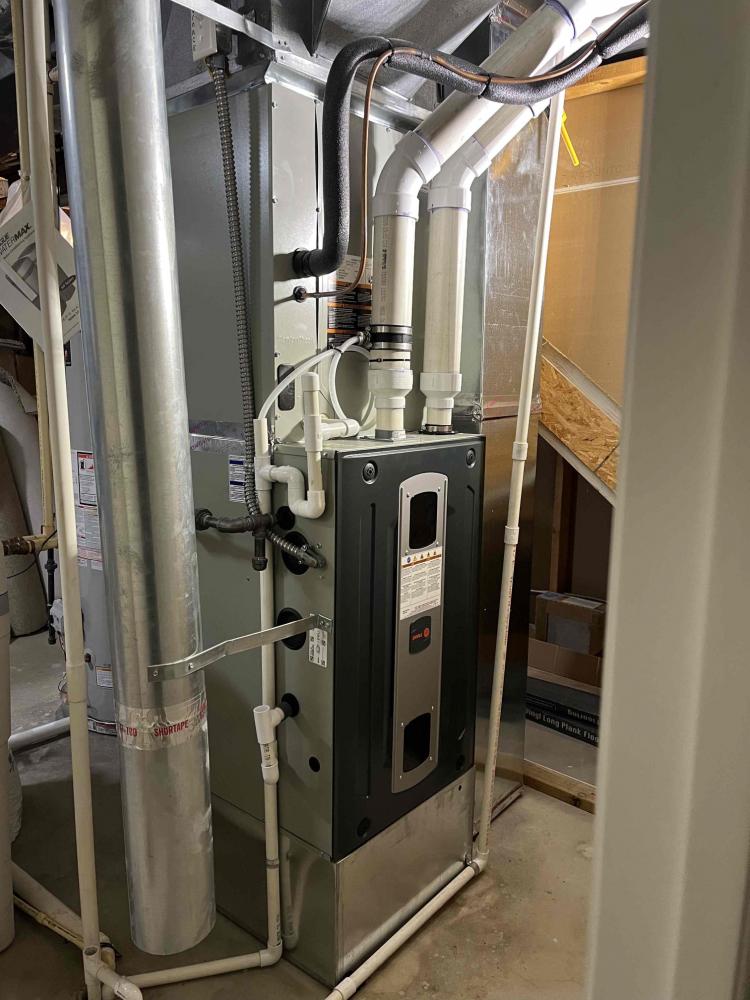 Upflow furnace in basement — air exits top
Source: Logan Services
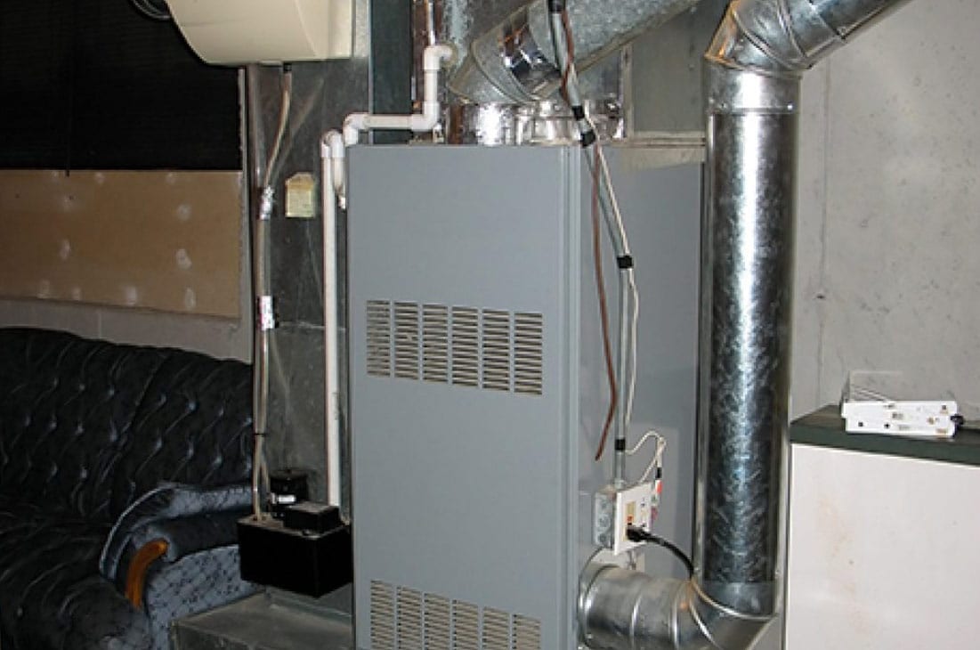 Upflow gas furnace — supply plenum on top
Source: Home Comfort Experts
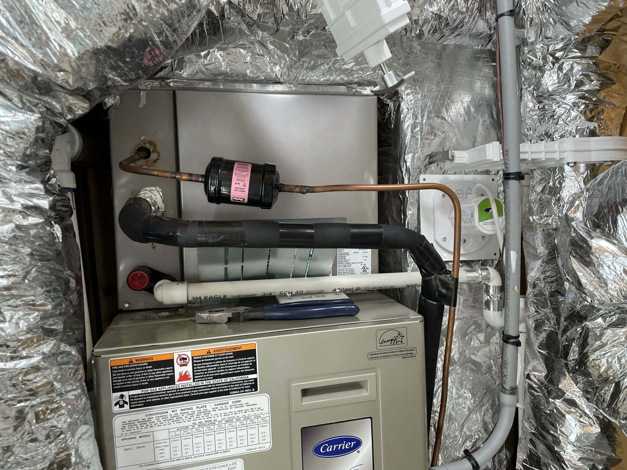 Carrier upflow with A-coil on top — UV mounts here
Source: CabinDIY Applying the Two Principles: In most upflow A-coils, the V-shape opens downward—meaning the return side (Option 2, below the coil) gives the lamp direct line-of-sight into the interior coil cavity where mold is worst, plus coverage of the drain pan sitting just below. Cooler return-side air also improves lamp output. The supply side (Option 1, above the coil) shines down on the apex of the A and treats conditioned air entering the ductwork—however, from above you’re looking at the ridge of the “A” rather than into the open V, so penetration into the interior coil cavity may be more limited. Both are effective—your installer should evaluate which side gives the best V-cavity access in your specific unit. Configuration 2: Horizontal Air Handler (Attic / Crawlspace / Garage Ceiling)
 Horizontal air handler in attic with flex duct
Source: High Performance HVAC
 Labeled suction & liquid lines on horizontal unit
Source: High Performance HVAC
 Horizontal airflow component orientation
Source: NRS Vegas Applying the Two Principles: In a horizontal system, the return-vs-supply distinction matters less for coil coverage since both sides offer similar angles. Focus on which side gives the best line-of-sight into the A-coil’s V-cavity. The drain pan sits at the bottom of the unit regardless of side—angle the lamp to reach it. Important: Do not position the lamp where it will shine directly on the air filter—UV-C degrades filter media, making it brittle. Configuration 3: Downflow Air Handler (Attic-Mounted — Feeds Down Through Floor/Ceiling)
 Downflow furnace installed in attic
Source: Family Handyman
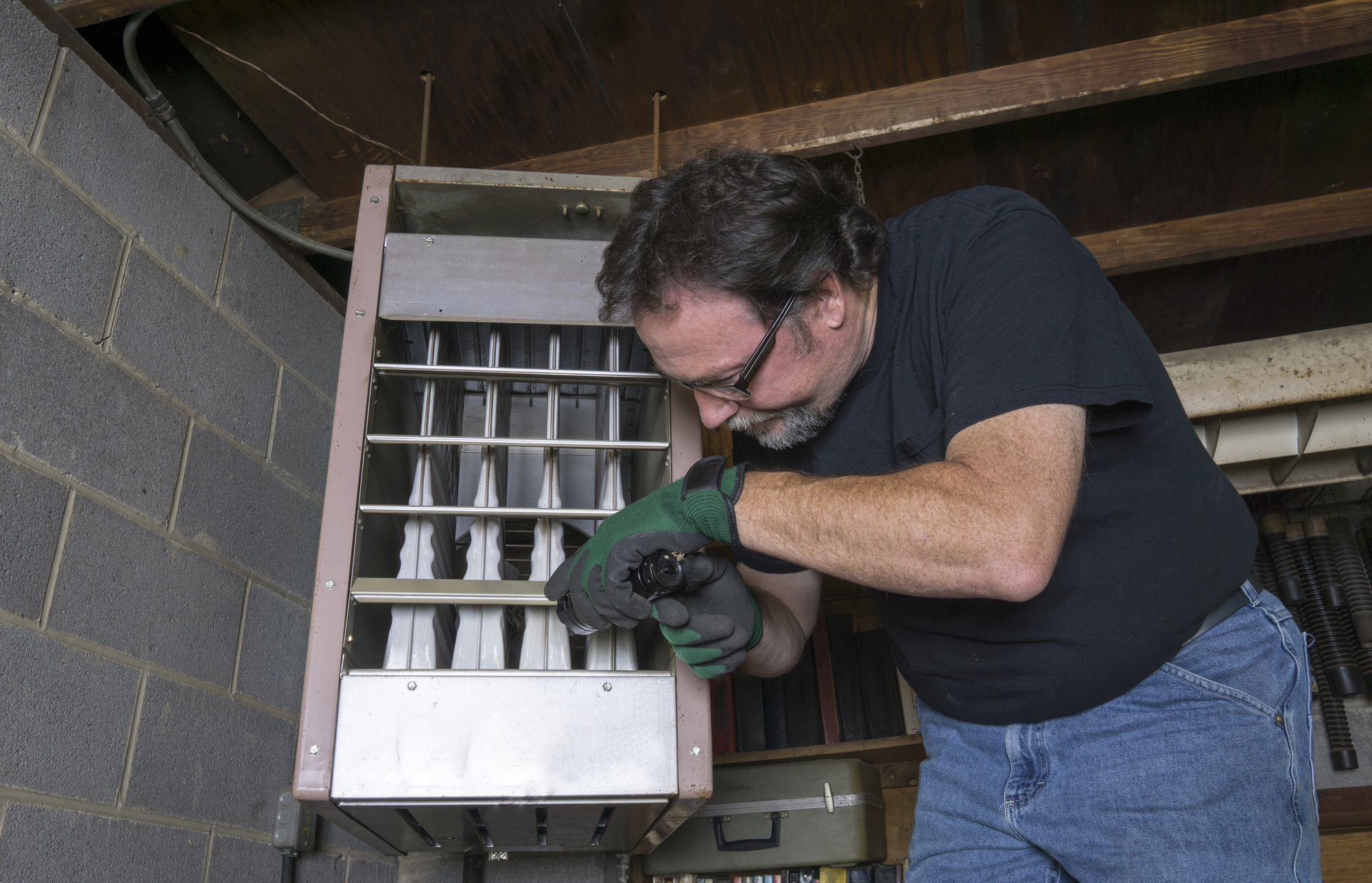 Gas furnace in attic — heat exchanger visible
Source: Valley Comfort
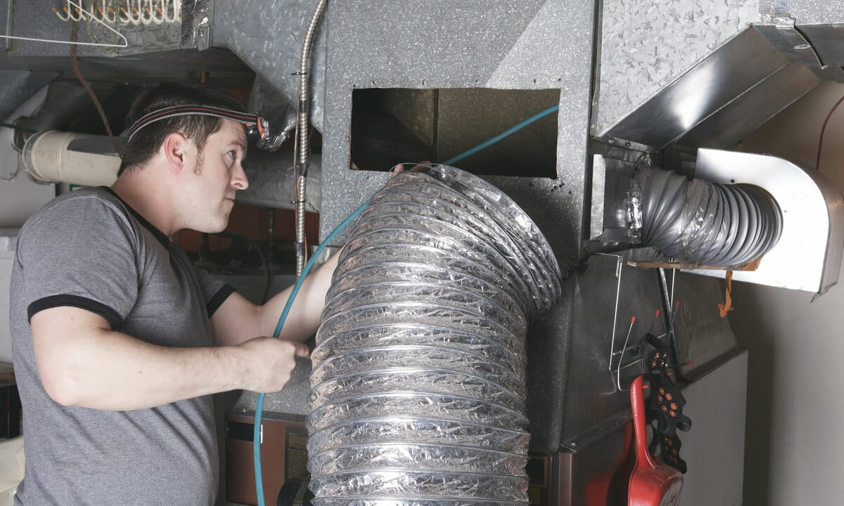 Connecting ductwork to attic-mounted unit
Source: Radiant Plumbing Applying the Two Principles: The supply side (Option 1, below the coil) is the clear winner in a downflow system. From below, the lamp faces upward toward both the coil underside and the drain pan—giving you direct coverage of both primary targets in a single placement. If the A-coil’s V opens downward (toward supply), you also get access into the interior coil cavity. The return side (above coil) would put the lamp far from the drain pan and potentially in line with the filter.
| Configuration | Recommended Side | Why |
|---|---|---|
| Upflow | Return side (below coil, after filter) | Direct access into V-cavity of A-coil + drain pan coverage + cooler air improves lamp output |
| Horizontal | Whichever side opens into V-cavity | Both sides similar; avoid shining on filter; angle toward drain pan at bottom |
| Downflow | Supply side (below coil) | Direct line-of-sight to both coil underside and drain pan from one position |
The universal principle: Prioritize the coil first, then the drain pan—and choose the side of the coil that gives you the best access into the interior V-cavity where mold growth is worst. That answer changes depending on your air handler’s orientation, which is why there is no single “best placement” that applies to every system. Your installer will evaluate your specific equipment to determine the safest and most effective position.
1st Supply Side of Evaporator Coil (Downstream) Within 12 inches of the coil face. This is the gold-standard placement endorsed by ASHRAE, Carrier, Fresh-Aire UV, and Field Controls.[1] The lamp directly irradiates the surface where mold is most aggressive. Must be wired to constant 24/7 power—not the blower relay—because mold grows fastest when air is still and the coil is wet.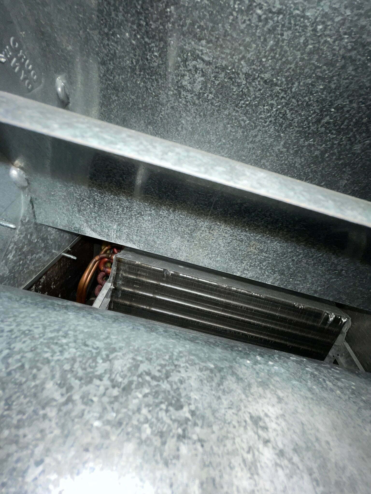 Inside supply plenum above A-coil — ideal mounting zone
Source: CabinDIY.com
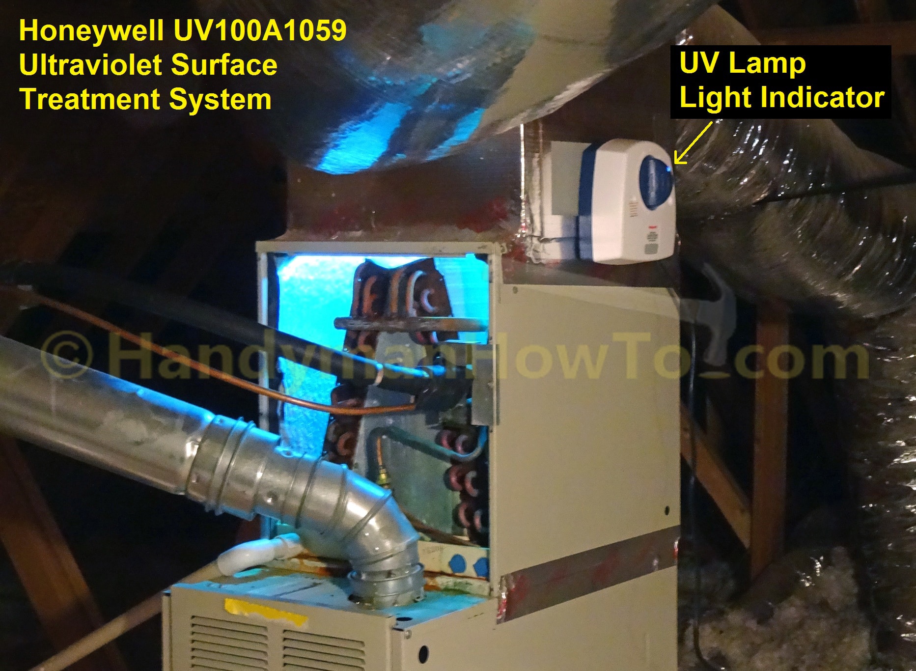 Honeywell UV lamp mounted above evaporator coils
Source: HandyManHowTo.com
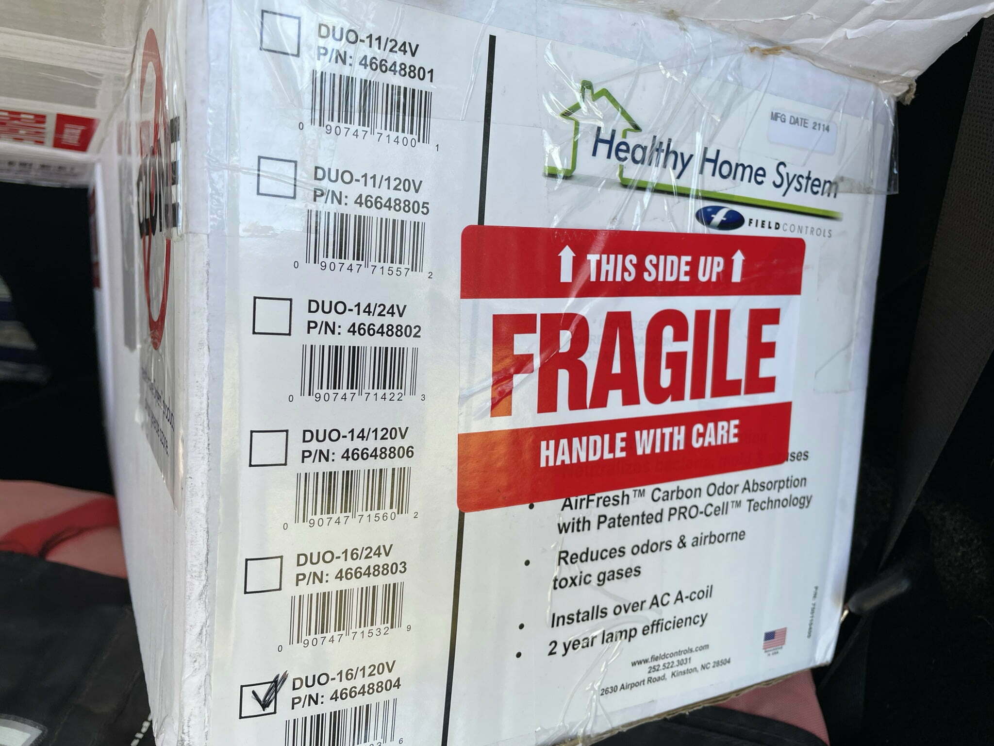
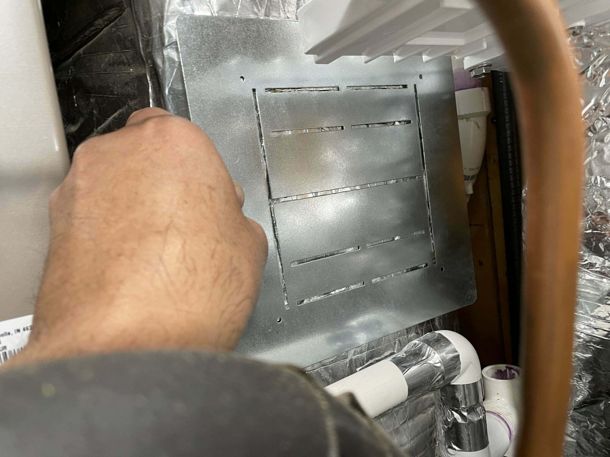
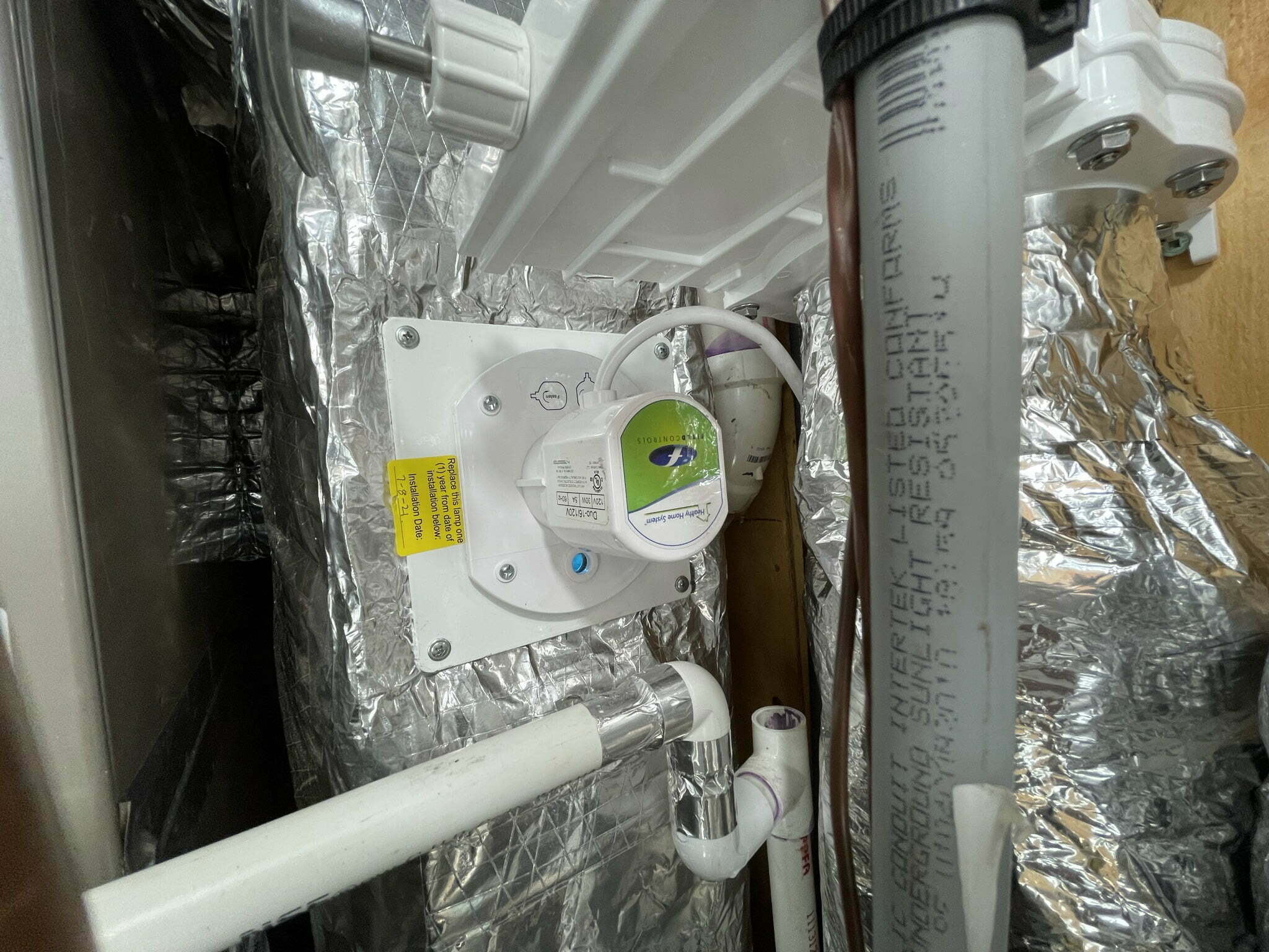 Field Controls UV-16 in supply plenum
Source: CabinDIY.com
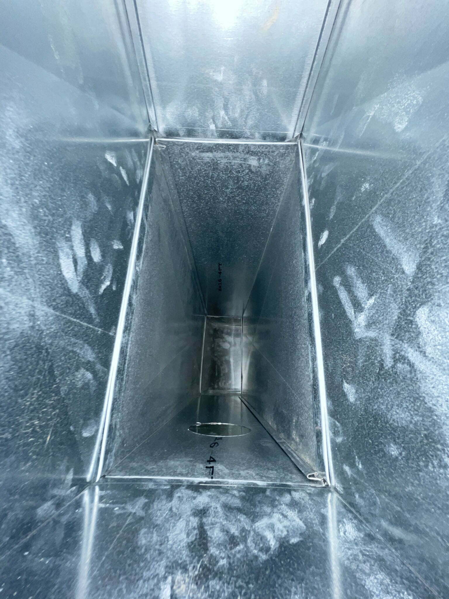 Supply-side ductwork with UV purifier position
Source: CabinDIY.com
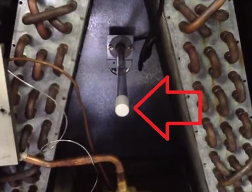 Optimal UV placement in air handler
Source: HVACHowTo.com 2nd Return Side of Evaporator Coil, After Filter Preferred in humid climates (especially Florida) where biofilm grows on the incoming side. Warmer return air (~80°F vs. ~55°F on supply side) improves UV lamp output by approximately 40%, since UV-C lamps are de-rated at lower temperatures.[13]
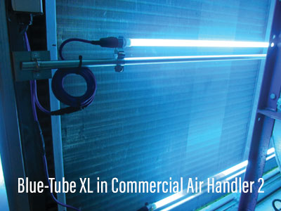
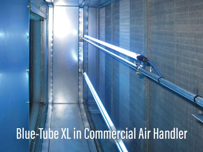 Fresh-Aire UV Blue-Tube XL in air handler
Source: FreshAireUV.com
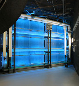
 Return-side positioning for coil & biofilm treatment
Source: FreshAireUV.com
 UV-C lamp illuminating return side of coil
Source: FreshAireUV.com
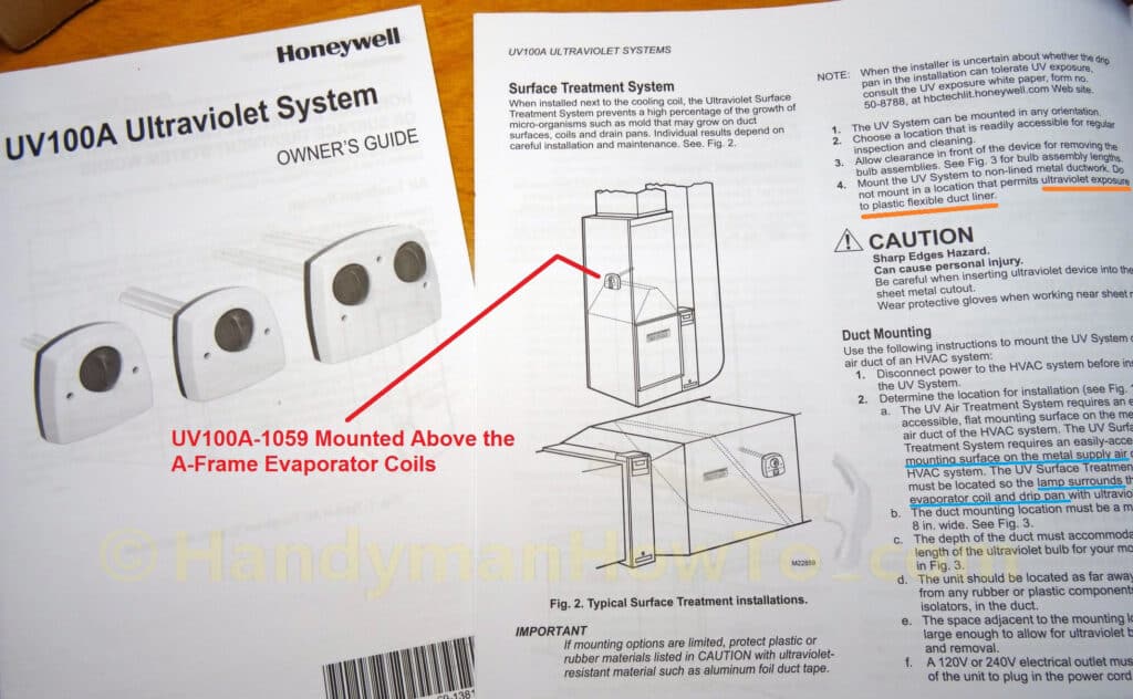 Placement diagram — lamp above A-coil frame
Source: HandyManHowTo.com
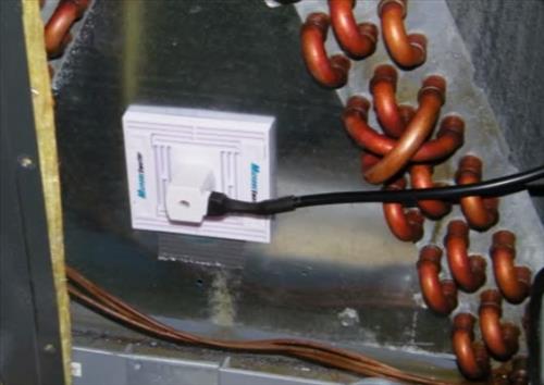 Inserting UV lamp into air handler
Source: HVACHowTo.com 3rd Return Air Duct, Downstream of Filter Prioritizes airstream treatment over coil irradiation. Air moves slower here, providing marginally better exposure time. Reserve for supplemental installations or when air handler access is impossible.
 Field Controls UV-16 in return ductwork
Source: CabinDIY.com
 Selecting duct-side mounting location
Source: CabinDIY.com
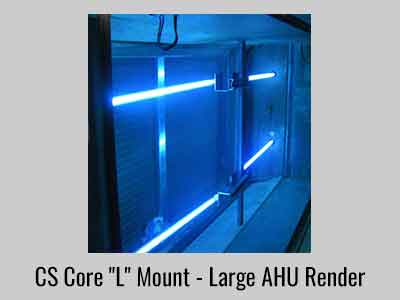 Fresh-Aire UV Core system in AHU duct
Source: FreshAireUV.com
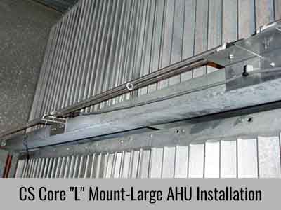 Commercial-scale UV-C duct installation
Source: FreshAireUV.com
 UV-C system in HVAC ductwork
Source: SmartService.com
What Your Installer Should Always Verify
UV lamp goes AFTER the air filter—at least 20 inches downstream. UV placed upstream of the filter gets fouled with dust and can destroy non-UV-rated filter media.[11] Applies to all 3 configurations — “after” means downstream in the airflow direction:• Upflow: lamp goes above the filter • Horizontal: lamp goes to the right of the filter • Downflow: lamp goes below the filter 12–14 inches from the coil surface for optimal irradiance distribution. Closer is not better—the light needs distance to spread across the coil face.[1] Applies to all 3 configurations. Measure 12–14″ from the coil face in the downstream direction—this is where the supply-side UV lamp sits (the gold “Above Drain Pan” position in each diagram above). Shield all non-UV-rated materials with aluminum foil tape—wiring insulation, plastic drain pans (pre-2013), flex duct, synthetic filter media, and zip ties. UV-C follows line-of-sight only.[11] Metal duct helps performance. Galvanized steel provides ~1.5× UV reflectance, aluminum ~1.75×. Your metal ductwork actually extends effective UV-C coverage through reflections.[14] UV Reflectance by Duct Material Aluminum Duct 1.75× Galvanized Steel 1.5× Ductboard 1.0× Flex Duct 0.5× Reflective metal ducts multiply effective UV-C dose at the coil; absorptive flex duct cuts it roughly in half.
What This Chart Means for You
The number on the x-axis is a UV reflectance multiplier. A value of 1× means the material reflects UV-C light equally in all directions (baseline). Higher is better — it means the duct walls bounce UV-C rays around inside the duct, increasing the total dose that hits passing air and surfaces. Lower means the material absorbs UV-C, reducing the lamp’s effective reach.
▲ Aluminum duct (~1.75×) — Best case. The UV-C lamp’s light bounces off aluminum walls and hits the coil and air from multiple angles. You get roughly 75% more UV-C exposure than the lamp alone. If your ductwork is already aluminum, this is a free performance bonus. ▲ Galvanized steel (~1.5×) — Second best. This is what most homes have. You still get a significant 50% UV-C boost from reflections. No action needed — your existing metal ducts are working in your favor. ▼ Ductboard (~0.9×) — Slightly below baseline. The fibrous surface absorbs some UV-C. The lamp still works on the coil, but you lose some of the “bonus bounce” effect. Not a dealbreaker. ▼ Flex duct (~0.4×) — Worst case. The corrugated plastic interior absorbs most UV-C. The lamp still irradiates the coil directly (its primary job), but reflected coverage in the ductwork is minimal.Do you need to do anything?
For most homeowners: no. The UV-C lamp’s primary job is irradiating the evaporator coil surface — that works regardless of duct material. The reflectance bonus is exactly that: a bonus. If you happen to have flex duct and want maximum air sterilization (not just coil treatment), your HVAC tech could install the lamp in a metal section of ductwork near the coil, or you could add a short aluminum plenum section. But for standard coil treatment, your existing ductwork is fine as-is.
Safety & Ongoing Maintenance
UV-C is safe when properly installed and maintained. These are the essential safety practices and maintenance commitments every homeowner should understand.
Safety Essentials
Never look directly at an operating UV-C lamp. UV-C causes arc-flash-equivalent eye damage. Even brief exposure can temporarily impair vision.[15] Turn off UV before any HVAC maintenance. This includes filter changes, coil cleaning, and any air handler access. A safety interlock switch on the access panel is recommended.[11] UV-C bulbs contain a small amount of mercury. Follow proper cleanup and disposal procedures if a lamp breaks.[16] No UV light should be visible through any return grilles, supply registers, or access panel gaps. Verify after installation.[11]Maintenance Commitment
9–12K Hours bulb life ~1 year of continuous use $50–150 Annual bulb cost Per replacementUV-C bulbs lose effectiveness after 9,000–12,000 hours, even if they still glow visibly.[17] This is the most common maintenance failure—industry professionals report that the majority of installed UV-C systems eventually run with degraded bulbs because homeowners forget to replace them. Mark your calendar for annual replacement.
"UV-C is proven technology that hospitals have used for decades. In your HVAC system, its primary job is keeping your evaporator coil—the dark, wet surface where mold loves to grow—completely clean. As a secondary benefit, it provides cumulative air treatment as your air recirculates multiple times per hour."
— Recommended Homeowner ExplanationYour UV-C Readiness Checklist
Use this checklist when evaluating UV-C for your home or reviewing an installer's proposal. A thorough installer should be able to address every item.
Before You Buy- What's your primary concern? (Mold/odor, allergies, general air quality, pathogen concerns)
- Does anyone in your home have allergies, asthma, or immune conditions?
- Do you notice musty smells when the system starts? (dirty sock syndrome indicator)
- What climate zone are you in? (Humid = strongest case for UV-C)
- Are you using at least a MERV 11 filter? (If basic fiberglass, upgrade first)
- When was the system last serviced or coil last cleaned?
- Are you prepared for $50–150/year in bulb replacements?
- What is my HVAC system tonnage? (From nameplate: "24" = 24,000 BTU = 2 tons)
- How many air handlers/zones does my home have? (Each needs its own UV)
- Is my system upflow, downflow, or horizontal configuration?
- What duct material is at the installation point? (Galvanized, aluminum, flex)
- Do I have sufficient internal clearance for the chosen model?
- For Magnetic Series: is the duct surface ferrous metal? (Magnet test)
- Lamp is positioned downstream of air filter (at least 20 inches)
- Lamp is 12–14 inches from coil face for optimal coverage
- All non-UV-rated materials are shielded with aluminum foil tape
- Drain pan is UV-rated (or shielded if pre-2013 system)
- Power is constant 24/7—NOT wired to the blower relay
- For communicating HVAC: separate 24VAC transformer used (not system transformer)
- No UV light visible through any grille, register, or access panel gap
- Safety interlock switch installed on access panel
- Drill hole sealed with included grommet/gasket—no air leaks
- Understand safety: never look at lamp, turn off before any maintenance
- Bulb replacement schedule: every 12 months for continuous operation
- Next replacement date noted: ___________
- You know how to verify the lamp is operating (view port or indicator)
- Realistic expectations set: proven coil cleaning + cumulative air treatment
- BioShieldUV ozone: 0.014 ppm—72% below EPA's 0.05 ppm limit[3]
UV-C Works—When Done Right
The professional HVAC community is candid: UV-C for coil sterilization is broadly accepted as effective, while UV-C for single-pass air purification remains debated due to limited dwell time at typical duct velocities.[5][6] The key to a successful UV-C installation is proper sizing, proper placement, and honest expectations.
Key Takeaway #1 Coil sterilization is the primary value. It's the application with the strongest evidence, broadest consensus, and most tangible results. Key Takeaway #2 Size matters enormously. Undersized UV is dismissed as "snake oil." Properly sized and placed UV-C is backed by ASHRAE data and decades of hospital use.[1] Key Takeaway #3 Replace the bulb annually. A degraded bulb still glows but provides no UV-C protection. Annual replacement is the single most important maintenance task."About 60–70% of the time they help. I find it interesting that often they say it didn't help, only to call a few weeks later saying they want one."
— Veteran HVAC Installer, on keeping a loaner UV unit for skeptical customers[6]References
- [1] ASHRAE (2019). ASHRAE Handbook—HVAC Applications, Chapter 62: Ultraviolet Air and Surface Treatment. American Society of Heating, Refrigerating and Air-Conditioning Engineers, Atlanta, GA.
- [2] Kowalski, W. (2009). Ultraviolet Germicidal Irradiation Handbook: UVGI for Air and Surface Disinfection. Springer-Verlag, Berlin. pp. 1–17.
- [3] U.S. Environmental Protection Agency (2023). "Ozone Generators that are Sold as Air Cleaners." EPA Indoor Air Quality. Available at: epa.gov/indoor-air-quality-iaq.
- [4] Fisk, W.J., Seppanen, O., Faulkner, D., & Huang, J. (2003). "Economizer System Cost Effectiveness: Accounting for the Influence of Building Type and Climate." Proceedings of Healthy Buildings 2003, Lawrence Berkeley National Laboratory, LBNL-53288.
- [5] ASHRAE (2020). ASHRAE Position Document on Airborne Infectious Diseases. American Society of Heating, Refrigerating and Air-Conditioning Engineers. Approved by ASHRAE Board of Directors, April 14, 2020.
- [6] HVAC-Talk Professional Forums; Reddit r/HVAC Community (2018–2024). Multiple threads on UV-C effectiveness for residential HVAC applications. Aggregated installer field reports and consensus perspectives.
- [7] Reed, N.G. (2010). "The History of Ultraviolet Germicidal Irradiation for Air Disinfection." Public Health Reports, 125(1), pp. 15–27.
- [8] ASHRAE (2017). ASHRAE Standard 52.2-2017: Method of Testing General Ventilation Air-Cleaning Devices for Removal Efficiency by Particle Size (MERV ratings).
- [9] Zhong, L., Haghighat, F., & Lee, C.S. (2015). "Ultraviolet Photocatalytic Oxidation for Indoor Environment Applications: A Review." Building and Environment, 94, pp. 395–402.
- [10] ACCA (2014). ACCA Manual J—Residential Load Calculation, 8th Edition. Air Conditioning Contractors of America.
- [11] Fresh-Aire UV (2022). UV-C Installation Best Practices Guide. Jupiter, FL. Includes material compatibility guidelines for UV-C exposure.
- [12] Harriman, L., Brundrett, G., & Kittler, R. (2001). Humidity Control Design Guide for Commercial and Institutional Buildings. ASHRAE. Chapter 4: Climate Zones and Moisture Loads.
- [13] Lau, J., Bahnfleth, W.P., & Mistrick, R.G. (2009). "Ultraviolet Irradiance Measurement and Modeling for Evaluating the Effectiveness of In-Duct UVGI Systems." HVAC&R Research, 15(2), pp. 271–287.
- [14] Kowalski, W. (2009). Ultraviolet Germicidal Irradiation Handbook. Springer. Chapter 10: UV Reflective Materials and Surface Characteristics.
- [15] International Commission on Non-Ionizing Radiation Protection (2004). "Guidelines on Limits of Exposure to Ultraviolet Radiation of Wavelengths Between 180 nm and 400 nm." Health Physics, 87(2), pp. 171–186.
- [16] U.S. Environmental Protection Agency (2023). "Cleaning Up a Broken CFL." EPA Mercury & Fluorescent Lamp Guidelines.
- [17] Philips Lighting (2019). TUV PL-L HF UV-C Germicidal Lamp Technical Specification. UV-C output depreciation curves: lamps retain ≥80% output at 9,000 hours, <65% at 12,000 hours.